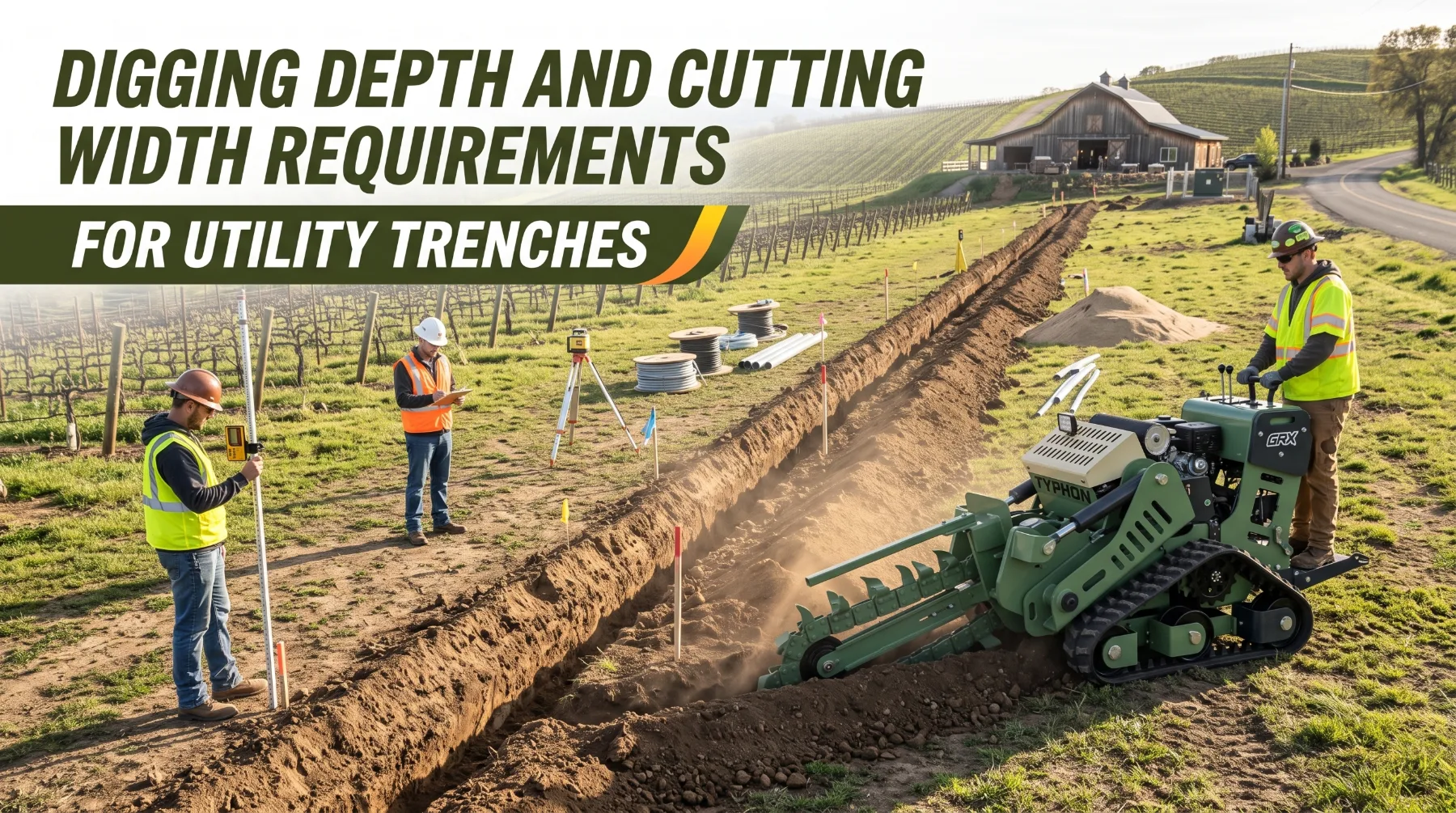
Utility trenches must meet the dimensions and layout specified for the services being installed. Electrical conduit, water pipes, drainage lines, and communication ducts each have different installation requirements, while bedding materials and separation distances also affect the space needed. Cutting a trench that is too shallow, too narrow, or poorly aligned can compromise the installation and lead to failed inspections, costly rework, and project delays.
Required depth depends on the service type, applicable codes, site conditions, and the planned finished ground level rather than only the surface present during excavation. Trench width must accommodate the installed lines, specified spacing, bedding, and enough working room for proper placement. Soil resistance also influences equipment selection, as compacted ground, rock, or mixed materials may require a different cutting chain and operating approach to maintain consistent dimensions.
Accurate trenching begins with reviewing construction drawings, utility specifications, grading plans, and applicable safety requirements. Survey marks, laser levels, and grade rods help operators maintain the required depth, while regular measurements confirm width and alignment along the route. Recording these checks before utilities are placed and backfill begins helps crews identify deviations early, meet inspection requirements, and reduce unnecessary excavation and rework.
Determining Required Trench Depth
Trench depth begins with determining how much cover the installed service requires. Cover is the distance between the top of the pipe, conduit, or cable and the finished ground surface above it. Adequate cover protects underground services from surface loads, frost, excavation work, and accidental damage. It also keeps lines at predictable depths so future crews can locate and avoid them.
Depth requirements vary by utility type and installation conditions. Electrical conduit and direct-buried cable requirements depend on the wiring method, voltage, and location under the electrical code adopted in the area. Lines beneath driveways, roads, and parking areas typically require more cover than those beneath lawns or landscaped areas. In cold climates, water lines are commonly buried below the local frost line to reduce freezing risks. Gravity sewer and drainage lines follow a designed slope, so their depth changes along the route. Gas lines, communications ducts, and irrigation mains follow their own standards, which may be established by the utility owner or project engineer.
Because requirements vary, determine the target depth from project documents rather than relying on habit or general rules. Review project drawings and trench details, utility owner specifications, applicable local codes and regulations, grading plans, and manufacturer installation guidelines for the specific pipe, conduit, or cable. These documents establish the required cover, trench profile, bedding thickness, and other installation conditions.
Finished grade is a common source of depth errors. Cover must be measured from the final ground surface, not the surface that exists on trenching day. If a parking lot, patio, or landscaped area will be lowered during later grading, the trench must be deep enough to preserve the required cover after the work is complete. Where fill will be added, the trench may be shallower only if the project documents permit it. Use surveyed finished-grade elevations and transfer them to the trench line with grade stakes, offset hubs, or a laser.
Total trench depth must also account for the pipe or conduit diameter and the specified bedding layer beneath it. For example, a water line requiring 36 inches of cover, with a 4-inch pipe and 4 inches of bedding, needs a trench approximately 44 inches deep. Joint trenches containing multiple services may require additional depth to maintain the specified vertical separation.
Where utilities cross existing lines, culverts, or foundations, project drawings may specify special depths, sleeves, or protective covers. Identify these crossings before trenching and confirm the required clearance with the engineer or utility owner.
Key Takeaway: Base trench depth on the installed service, required cover, project drawings, utility specifications, and applicable local requirements. Always measure cover from finished grade rather than the existing ground surface.
Selecting the Correct Cutting Width
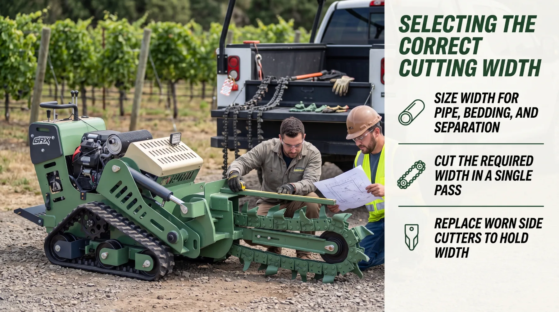
Trench width affects nearly every stage of installation. The excavation must accommodate the pipe, conduit, or cable protection, along with the specified bedding, separation, and working clearance. Keeping the trench within the required width also limits unnecessary excavation and restoration work.
A trench that is too narrow makes installation more difficult because pipes and conduits may not sit properly on the trench bottom, while fittings, couplings, and bell ends may not have enough room. It can also prevent crews from placing and compacting bedding material correctly around the pipe. In joint trenches, insufficient width may make it impossible to maintain the required separation between services, such as electrical lines and water pipes. These problems can force workers to widen the trench manually or make another cutting pass, increasing labor costs and potentially damaging the trench walls.
Excessive width creates additional excavation, spoil handling, backfilling, compaction, and surface restoration work along the entire route. Wider trenches disturb more lawns, paving, and planting areas and may increase the cost of select backfill or flowable fill. In certain pipe installations, excess width can also affect how surrounding soil loads act on the pipe, making compliance with the engineer's or manufacturer's specified width range important.
Determine the required width from the project specifications. Start with the outside diameter of the largest pipe or conduit, or the combined width of the services in a joint trench. Add the specified clearance for bedding placement, compaction, and separation. Project drawings may provide these dimensions directly, while pipe manufacturer guidelines and utility specifications can establish the minimum and maximum acceptable widths.
The chain and tooth configuration determine the actual cutting width of a chain trencher. Select a chain that can produce the required width in a single pass, and inspect the side-cutting teeth regularly. Worn side cutters can gradually narrow the trench even when the change is difficult to see from the surface. On longer projects, measure the trench periodically to confirm that the width remains within specification.
Width also influences worker access and installation efficiency. Crews may need sufficient room to connect pipes, place bedding, or tie into existing lines. If workers must enter the excavation, the trench must also satisfy applicable access and protective system requirements.
Key Takeaway: Select a cutting width that accommodates the pipe or conduit, bedding, separation, and required installation clearance. A trench that is too narrow complicates installation, while excessive width increases excavation and backfill costs.
Soil Conditions and Trench Dimensions
Soil conditions directly affect a trencher's ability to maintain the specified depth and width along the route. Soil type, compaction, moisture, and buried obstructions influence how the chain cuts and how well the trench retains its shape after excavation.
Loose sand and loam generally cut easily, allowing the trencher to advance quickly. However, loose material may slide back into the trench, filling the bottom and widening the upper section. Crews may need to install the pipe and bedding soon after excavation while keeping spoil piles well away from the edge.
Clay can hold clean, vertical trench walls when conditions are suitable, helping maintain width. Wet clay, however, may stick to the chain, teeth, and spoil auger, increasing resistance and slowing production. Dry, hard clay can also resist penetration and cause the chain to ride upward or move off line when the operator advances too quickly.
Compacted ground, including old roadbeds, driveways, haul routes, and engineered fill, requires greater cutting force. If the teeth are unsuitable or the ground drive moves too quickly, the chain may skate across the surface and leave the trench shallower than intended. Regular chain tooth maintenance is essential for consistent cutting performance. The operator should inspect the teeth for wear, damage, or missing components and replace worn teeth as needed to maintain effective ground penetration. Gravel, cobbles, and rock create additional challenges because coarse material accelerates tooth wear, particularly on side cutters. Cobbles and fractured rock can deflect the chain, causing the trench to wander or leaving an uneven bottom, while solid rock may exceed the capability of a standard cutting chain.
Moisture and groundwater can further affect cutting accuracy and trench stability. Wet soil may build up on the cutting system and reduce traction, causing the machine to drift off line. Water entering the excavation can weaken the trench walls and trigger collapse even after the trench has been cut to the correct dimensions. Saturated conditions also make bedding placement and compaction more difficult.
Buried roots, old concrete, abandoned pipes, wire, and other debris can stall the chain or deflect it unexpectedly. These obstructions may cause sudden changes in depth, width, or alignment, so inspect the route for potential hazards before excavation begins.
Difficult ground affects both production speed and dimensional consistency. Match the machine and cutting system to the expected soil conditions, and adjust operating technique as conditions change. Review available soil information, probe the route where appropriate, and look for signs of rock, old fill, or wet areas. In mixed ground, reduce the ground drive speed when necessary to let the chain cut cleanly rather than forcing it through resistant material. Increase inspection frequency in challenging sections.
Trench stability can also change throughout the workday. Rain may soften the walls, while vibration can loosen the surrounding soil. Monitor the excavation for sloughing, cracks near the edge, and water seepage, even when the trench initially holds its shape.
Key Takeaway: Soil type, compaction, moisture, and buried obstructions affect cutting performance and dimensional consistency. Match the equipment to site conditions, adjust operating speed when necessary, and verify trench dimensions more frequently in difficult ground.
Underground Utility and Safety Requirements
Utility trenching takes place in ground that may already contain buried services, while the excavation itself introduces hazards for workers and nearby equipment. Accurate dimensions are not enough if the work damages an existing utility or exposes workers to unsafe conditions. Utility identification and trench safety must be included in the work plan from the beginning.
Before excavation, contact the applicable one-call locating service. In the United States, calling 811 connects excavators with the appropriate locating process. Provide accurate details about the dig area, allow the required response period, and confirm that all expected utility owners have responded before digging. Waiting periods and marking requirements vary by state, so follow the rules that apply to the project.
Public locating services generally mark utilities operated by participating utility owners, but private lines may remain unmarked. These can include landscape lighting, irrigation systems, private water and sewer laterals, and services running to outbuildings. Review site plans with the property owner and arrange private utility locating when additional underground services may be present.
Utility markings indicate approximate locations rather than exact positions. Many jurisdictions establish a tolerance zone around marked lines, often 18 to 24 inches on either side, where mechanical excavation is restricted. Confirm the applicable local requirements and expose utilities within the designated zone through careful hand digging or vacuum excavation before trenching across or alongside them. Verify the depth of existing lines at crossings because their position may affect the new trench's depth and required separation.
Stop work immediately if the chain contacts an unmarked line, warning tape, or an unidentified obstruction. Keep personnel clear of the area and follow the site's utility emergency procedures. Treat unknown lines as potentially active until the responsible utility owner confirms their status.
Trench stability must also be assessed. A competent person should evaluate soil conditions and determine the protective measures required under applicable regulations. In the United States, federal OSHA rules generally require a protective system for trenches 5 feet deep or more unless the excavation is made entirely in stable rock. Shallower trenches may also require protection when a competent person identifies a potential cave-in hazard.
Protective systems can include sloping, benching, shoring, and shielding, depending on the soil, excavation, and applicable rules. Under federal OSHA requirements, trenches 4 feet deep or more generally need a ladder, stairway, ramp, or other permitted means of egress positioned so workers do not travel more than 25 feet laterally to reach it. Never allow workers to enter an excavation that has not been evaluated and protected as required.
Keep spoil piles and materials at least 2 feet from the trench edge, or farther away when the site safety plan requires it. Position the trencher and other equipment at a safe distance from the edge, and barricade or cover open trenches when work pauses. Keep workers and bystanders clear of the moving chain, boom, and spoil discharge area. Never step over the boom or reach toward the chain while it is running, and shut down the machine completely before approaching the cutting assembly.
Protective systems, access provisions, spoil placement, and other safety measures must comply with the site plan and relevant regulations, particularly when workers need to enter the trench to connect services or place bedding.
Key Takeaway: Identify underground utilities before excavation and follow applicable requirements for trench protection, access, and spoil placement. Pay particular attention to safety whenever workers must enter the trench.
Verifying Trench Dimensions and Quality
Regular trench inspections help ensure excavation meets project requirements for depth, width, alignment, and grade. Identifying deviations early reduces rework and helps prepare the trench for safe, accurate pipe or utility installation.
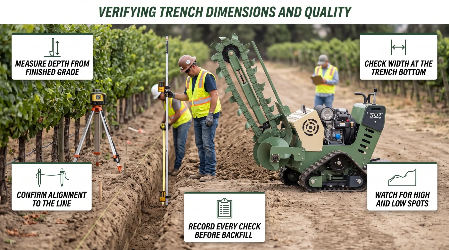
- Depth and Width: Measure trench depth and bottom width against project specifications. Account for pipe diameter, bedding thickness, required cover, and utility separation.
- Alignment and Grade: Check the cutting path against survey marks or string lines. Confirm the trench follows the required route and slope, especially for gravity drainage systems.
- Inspection Frequency: Check dimensions at planned intervals, changes in grade or direction, utility crossings, and after replacing cutting teeth or chains. Adjust inspection frequency to suit site conditions and project requirements.
- Safe Measurement: Use grade rods, laser equipment, or other suitable tools from outside the trench whenever possible. Never enter an unprotected trench, and stop the machine before approaching the cutting system.
- Documentation and Corrections: Record measurements, locations, and corrective work. Recut shallow sections, widen narrow areas, and remove loose soil, rocks, and standing water before preparing the trench for installation.
Key Takeaway: Verify trench depth, width, alignment, and bottom consistency at regular intervals. Record measurements, correct deviations promptly, and confirm the trench is clean and ready before installing utilities.
Conclusion
Utility trenching succeeds when depth and width are planned from the start and confirmed throughout the work, and the crews that deliver consistent results treat dimensions as part of the installation rather than an afterthought: required depth comes from the installed service, the cover it needs, project drawings, utility specifications, and applicable local codes, measured from finished grade so future grading doesn't leave lines too shallow. Cutting width must accommodate pipe, conduit, bedding, and separation without adding unnecessary excavation and backfill, while soil conditions, from loose sand to compacted clay and fractured rock, shape how well a trencher holds those dimensions along the full route. Choosing equipment with the depth capability, cutting width, power, and access the job requires, confirmed against the manufacturer's specifications, sets the foundation for accurate excavation. Locating every existing utility, exposing lines in the tolerance zone, and following trench protection and access requirements keep the crew and surrounding infrastructure safe, and regular verification of depth, width, alignment, and consistency catches deviations before they become costly rework. When you plan carefully and measure consistently, you deliver installations that pass inspection, protect the services inside them, and earn the confidence of the customers who depend on your work. Before your next utility trench, review the drawings and grading plan, confirm the required cover and width, match your trencher and cutting system to the soil, call the locating service, and set a checking routine that proves every section meets specification before backfill.
Frequently Asked Questions
What determines utility trench depth?
The required utility trench depth depends on the type of service being installed, minimum cover requirements, project specifications, soil conditions, and applicable regulations. Cover is generally measured from the finished ground surface to the top of the installed pipe or conduit, while total trench depth must also account for the pipe diameter and any specified bedding layer. Confirming these requirements before excavation helps ensure the trench provides adequate protection and meets the installation standards.
How is trench cutting width selected?
Trench cutting width should provide enough space for the pipe or conduit, required bedding, installation clearance, and any specified separation between utilities. Project drawings, utility standards, local requirements, and pipe manufacturer guidelines typically define the acceptable width range. The selected width should also suit the installation method and ground conditions without removing unnecessary soil. Confirming these details before trenching helps prevent installation difficulties, excess excavation, and additional backfilling work.
Can one trencher create every trench size?
No. Trenchers vary in their maximum cutting depth, available chain widths, engine power, and ability to handle different soil conditions. The selected machine must be capable of producing the required trench dimensions under the actual conditions along the route. Some projects may require a different cutting chain, a larger machine, or an alternative excavation method where the ground is particularly hard or obstructed. Checking equipment specifications before work begins helps avoid delays and incomplete excavation.
Why should trench dimensions be checked during excavation?
Checking trench dimensions at regular intervals helps maintain the specified depth, width, and alignment throughout the excavation. Variations can occur because of worn cutting teeth, changing soil resistance, uneven ground, or differences in the planned grade. Measuring at set points allows operators to identify deviations early and make corrections before they affect pipe placement or other installation work. Consistent checks help reduce rework, unnecessary material removal, and problems during bedding, installation, and backfilling.