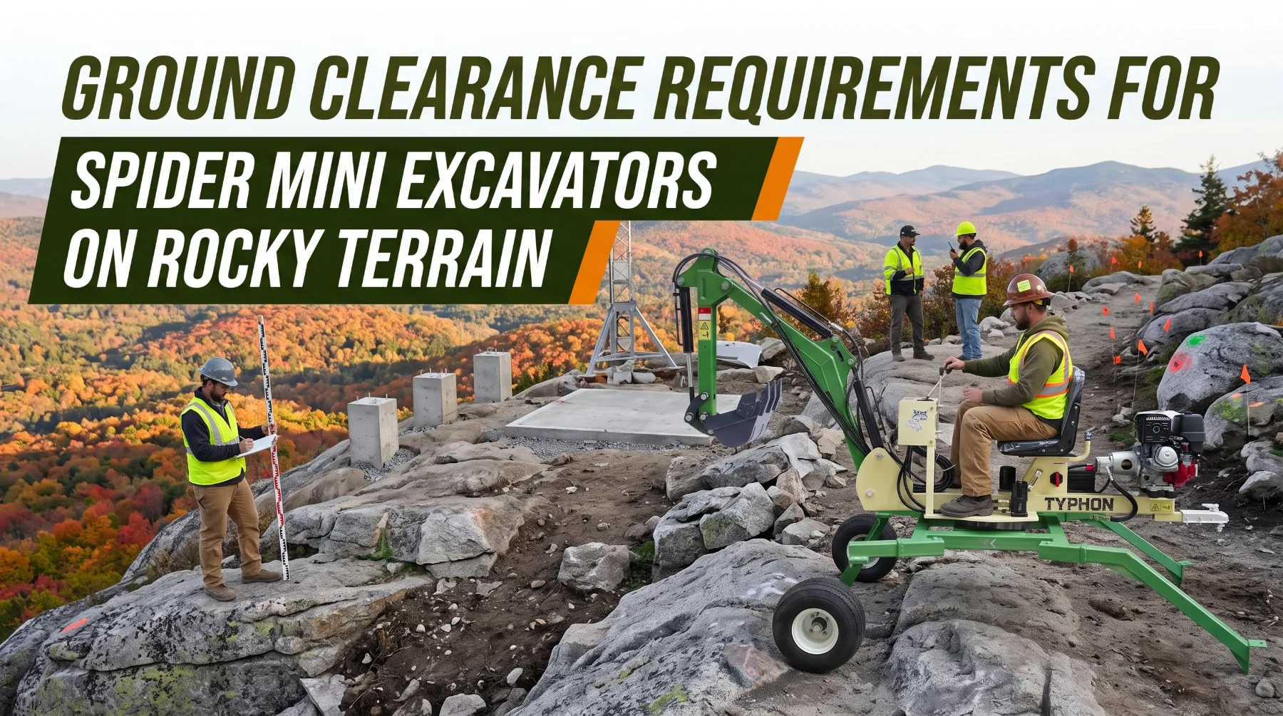
Ground clearance is an important factor when operating spider mini excavators on rocky construction sites, steep landscapes, and uneven ground. These compact machines are designed for work in restricted areas and, depending on the model, may use independently positioned support legs to establish a stable working position on challenging terrain. However, rocks, exposed roots, ledges, and sudden changes in elevation can interfere with movement or contact the undercarriage. Understanding ground clearance helps contractors evaluate access routes, identify potential obstacles, and determine whether the machine can safely reach the work area. Safe operation also requires attention to ground strength, support-leg placement, track condition, slope limits, and the manufacturer's instructions for the specific model.
Understanding Ground Clearance
Ground clearance refers to the distance between the supporting ground surface and the lowest relevant part of a machine in a specified configuration. For a spider mini excavator, this measurement can help determine whether the undercarriage or other low-mounted components may contact rocks, raised ground, or uneven sections along a travel route. However, the actual clearance depends on the machine's design, undercarriage arrangement, and operating configuration.
Published specifications should be checked before planning access across rocky terrain. Different spider excavator models may have different ground clearance measurements, track dimensions, support-leg arrangements, and travel configurations. Contractors should use the specifications for the exact machine rather than relying on general measurements from another model. The manufacturer's operating manual may also explain how configuration changes affect clearance and safe movement.
Ground clearance should not be considered separately from the machine's overall dimensions. A machine may have sufficient clearance beneath one part of the undercarriage but still encounter interference from its tracks, support legs, boom, or other components. The distance between obstacles also matters because a narrow passage may restrict the machine even when the ground beneath it is relatively level. Contractors should evaluate the entire machine envelope when planning access.
Another important consideration is that ground clearance does not establish whether an obstacle can safely support the machine. A rock may be lower than the available clearance but still shift under track pressure or support-leg loading. Similarly, a shallow depression may create a stability concern if one side of the undercarriage settles unexpectedly. Clearance measurements should therefore be used alongside an assessment of obstacle shape, ground stability, and the manufacturer's travel limits.
Assessing Rocky Obstacles
Rocky terrain can contain a wide range of obstacles, including loose stones, large boulders, exposed bedrock, sharp ledges, and irregular ground transitions. Their dimensions and positions can affect how a spider mini excavator moves across the site. A rounded rock may roll when loaded, while a sharp-edged boulder may damage a rubber track or interfere with undercarriage components. Uneven bedrock can also create abrupt changes in elevation that affect track contact and machine balance.
Evaluating an obstacle requires more than measuring its height. Contractors should consider its shape, stability, orientation, and relationship to nearby terrain. A rock positioned directly beneath a low component may cause contact even if it appears relatively small. Several closely spaced rocks can also create a difficult passage because the tracks or support legs may not have enough room to settle on suitable ground.
Loose stones and fractured rock deserve particular attention because they may shift when the machine travels over them. An obstacle that appears firm from a distance may rest on loose soil or unstable material. If it moves beneath a track or support point, the machine may lose stable contact with the ground. Operators should avoid relying on loose rocks as a dependable travel surface or support foundation.
Before crossing an unfamiliar section, operators should inspect the intended route and identify safer alternatives where possible. Removing a small loose obstruction or preparing a suitable path may reduce the risk of undercarriage damage, provided the work can be performed safely. Large rocks, unstable ledges, and obstacles that exceed the manufacturer's permitted travel conditions should not be crossed simply because the machine appears capable of clearing them. When the route cannot be assessed confidently, work should pause until a safe approach is established.
Positioning Support Legs on Uneven Ground
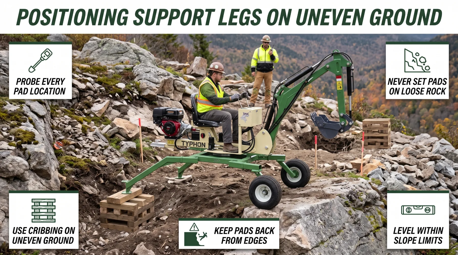
Some spider mini excavators use individually positioned support legs to establish a suitable working position on uneven terrain. This arrangement can help the machine adapt to certain slopes and changes in ground elevation within its approved operating range. However, the legs must be positioned according to the manufacturer's instructions, and each support point must rest on ground capable of carrying the applied load.
Rocky terrain creates specific challenges for support-leg placement. A leg positioned on a loose boulder, fractured rock, or unstable soil may shift as the excavator begins digging. Even a small movement at one support point can change the machine's balance and affect the forces acting on the boom and attachment. Contractors should identify stable support locations before positioning the machine and avoid using loose material as a foundation.
The ground beneath each leg should be evaluated for strength, slope, and the risk of movement. Where permitted by the manufacturer and suitable for the site, approved support pads or other specified load-distribution measures may help spread pressure over a larger area. Such measures must not be treated as a substitute for stable ground or proper machine setup. The correct support method depends on the excavator design, the loads involved, and the manufacturer's requirements.
Operators must also confirm that the machine remains within its permitted operating configuration. The ability to position the legs independently does not mean the excavator can safely work at any angle or reach across any obstacle. Boom extension, attachment position, digging force, and material loads can affect stability during operation. If the support legs cannot be placed securely or the ground begins to shift, the operator should stop and reassess the setup before continuing.
Managing Travel and Excavation Movements
Safe movement on rocky terrain requires coordination between route planning, machine positioning, and excavation technique. Before traveling, operators should identify the intended path, evaluate obstacles, and determine whether the ground can support the machine's weight. They should avoid narrow ledges, loose rock piles, unstable excavation edges, and areas where one track could settle into a depression. A route that appears shorter may be less suitable if it requires crossing obstacles that threaten clearance or stability.
Controlled travel helps the operator respond to changes in the ground. Sudden steering inputs or rapid movement over uneven surfaces can disturb track contact and cause the machine to shift unexpectedly. Operators should maintain a speed appropriate for the terrain and follow the manufacturer's instructions for travel on slopes. If the machine begins to slip, sink, or lose stable contact, continued movement may worsen the situation. The operator should stop when safe and follow the prescribed procedure for reassessing the route.
Excavation movements can also influence machine stability. Extending the boom or moving a loaded bucket away from the machine changes the forces acting on the undercarriage and support system. Digging close to an unstable rock face, steep edge, or unsupported section of ground can introduce additional hazards. Operators should position the excavator so the intended digging movements remain within the machine's permitted operating limits and avoid placing unnecessary loads on uncertain ground.
The work area should be reassessed as excavation progresses. Removing soil or rock can change the support available beneath tracks or support legs, while newly exposed material may be loose or fractured. Spoil piles, temporary access routes, and nearby equipment can also restrict movement or introduce additional loading near an edge. When conditions change, operators should adjust the plan rather than continuing with the original setup automatically. If safe positioning cannot be maintained, the task should stop until an appropriate alternative is established.
Inspections and Jobsite Planning
Effective jobsite planning begins before the spider mini excavator reaches the work area. Contractors should review access width, overhead clearance, ground elevation, obstacle dimensions, slope, and the condition of the intended travel surface. They should also identify nearby trenches, excavations, rock faces, buried utilities, and other hazards that may affect machine movement or support. Planning these details in advance can reduce unnecessary repositioning and help prevent the machine from entering an unsuitable area.
Pre-operation inspections should cover the components that influence clearance, mobility, and stability. Tracks, undercarriage structures, support legs, joints, pins, hoses, and visible protective components should be checked for damage or abnormal wear. Operators should confirm that the relevant controls and safety systems function as intended and that the machine is configured according to the operating manual. Any issue that could affect safe operation should be addressed before work begins.
Ground conditions can change throughout the day due to rainfall, excavation, vibration, and repeated machine travel. Contractors should monitor these changes and reassess support locations and access routes whenever the surface becomes unstable or obstacles move. Rocky terrain may also conceal weak soil pockets, voids, or loose material beneath the visible surface. Operators should not assume that ground is stable simply because it appears solid from above.
Maintenance records and jobsite observations can help improve future planning. Documenting track damage, repeated undercarriage contact, support-leg movement, and difficult access points can reveal recurring problems. Contractors can use this information to improve route selection, schedule inspections, and determine whether a different machine configuration or excavation method is more suitable. Throughout the process, the manufacturer's operating limits must remain the primary reference for safe setup, travel, and digging.
Protecting Tracks and Undercarriage
The undercarriage is exposed to repeated contact with soil, rock, debris, and changes in ground elevation. On rocky jobsites, sharp edges and uneven surfaces can increase the risk of cuts, abrasion, impact damage, and abnormal wear. Depending on the machine design, vulnerable areas may include track components, rollers, exposed hoses, protective covers, and structural parts positioned close to the ground.
Track condition influences both mobility and stability. Worn tread, damaged rubber, loose components, or unsuitable track tension can affect the machine's ability to maintain reliable contact with the ground. When a track rides over a sharp rock or becomes caught between obstacles, continued movement may worsen the damage. Operators should avoid forcing the machine forward when the undercarriage is obstructed or when the tracks begin slipping unexpectedly.
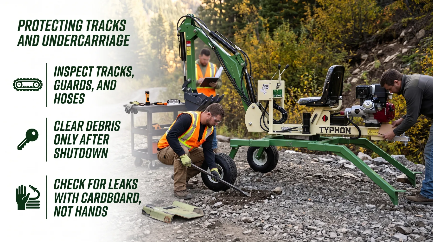
Travel technique also affects undercarriage wear. Sudden acceleration, sharp turns, and repeated attempts to climb over an unsuitable obstacle can increase stress on tracks and other components. Operators should move at a controlled speed, use smooth control inputs, and select a route that minimizes unnecessary impacts. They should also follow the manufacturer's instructions for travel direction and any restrictions that apply to uneven or sloping terrain.
Post-operation inspection is particularly valuable after working on rocky ground. Operators should check for trapped stones, cuts, abnormal wear, damaged protective components, and signs of impact. Debris should be removed using the approved cleaning procedure after the machine has been safely shut down. Any damage that could affect safe movement or structural integrity should be assessed before the excavator returns to service. Routine maintenance cannot eliminate all terrain-related risks, but it can help identify problems before they lead to unexpected downtime.
Conclusion
Ground clearance is an important factor when using spider mini excavators on rocky terrain, but it is only one part of safe machine operation. Obstacle height, rock stability, track condition, support-leg placement, slope, and ground strength all influence whether the excavator can travel and work safely. Contractors should verify the specifications for the exact model, inspect access routes, and identify suitable support locations before starting work. Controlled travel, careful excavation movements, and regular undercarriage inspections can help reduce equipment damage and unexpected downtime. Because rocky conditions may change as excavation progresses, operators should continue assessing the site and stop whenever the machine can no longer be positioned safely. Matching the machine's capabilities to the terrain and following the manufacturer's instructions helps support reliable operation on challenging jobsites.
Frequently Asked Questions
Why is ground clearance important on rocky terrain?
It affects how much space is available beneath the machine when moving over uneven surfaces and obstacles. On a spider excavator, clearance also changes with leg configuration, and a long hump or ledge crest can catch the chassis even when it measures below the stated figure. Measure your machine's real clearance in the stance you'll use and plan your route around that figure.
Can an excavator cross any rock that is lower than its ground clearance?
No. Obstacle shape, stability, machine configuration, and the position of tracks or support legs also matter. A long rounded hump can catch the chassis between legs even when shorter than the clearance figure, and a loose rock can roll under a leg or track. Assess height, shape, stability, and position, then decide whether to cross, prepare, or route around each obstacle.
How can operators protect the undercarriage?
Inspect routes, remove sharp and loose rock from the travel path, ramp ledge humps with compacted crushed stone, travel slowly in the manufacturer's recommended configuration, avoid pivoting tracks on sharp rock, use only approved guards, and inspect tracks, guards, hoses, and leg cylinders after every rocky shift with the machine shut down and the key removed.
What should contractors assess before working on rocky ground?
Check access width, ground stability, slopes, obstacle clearance, support-leg placement options, and the manufacturer's operating limits. Walk the full route with dimensional drawings and a gauge stick, identify loose rock above planned excavations, locate buried and overhead utilities, plan firm support for every leg, review weather, and confirm the operator is trained on the exact machine.